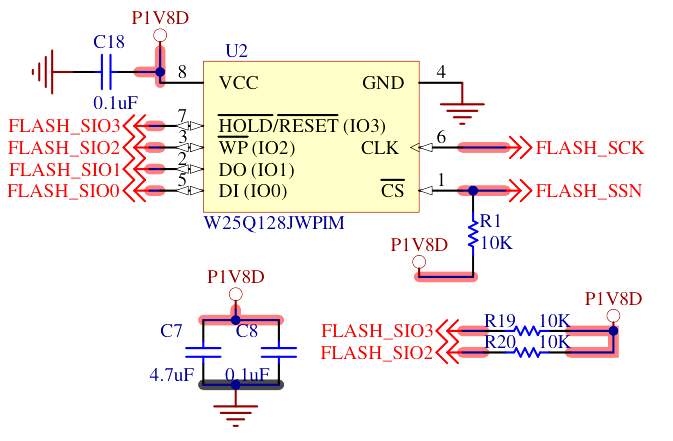
A 32 MByte (256 Mbit) QSPI flash with Dual Transmission Rate (DTR) can store the FPGA bitfile as well as a storing the firmware that the soft CPU core can execute in-place (XIP).

In the default RTL, the flash is mapped at address 0x2000_0000.
Programming with ecpprog
The command ecpprog permits to send a bitfile to the SoM by using the FTDI present on the Devkit.
It can be installed as part of OSS Cad Suite then called this way:
The power cycle the board to let the FPGA start.
The -o 0x000000 can be adapted to any local offset within the flash, to allow multiple binary images to cohabitate.
Programming with Lattice Radiant Programmer
The regular Radiant programmer can also be used as usual for Lattice parts.
- Download, install and run Lattice Radiant
- From the toolbar, select
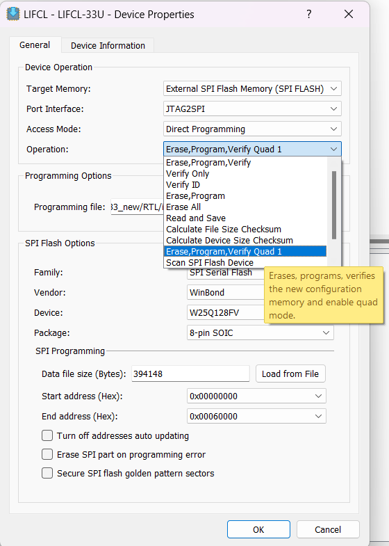
Tools > Programmer, the Programmer will start - From the programmer, a table of operations will be shown full-width, with various fields that can be set: Set "Device Family" to "LIFCL", "Device" to "LIFCL-33U", "Operation" will open a window
- From the window that opens, set to "Operation" to "Erase, Program, Verify Quad 1", "Programming file" to the file you want to load.
- Clic on the "Load From File" button to let Radiant Programmer fill the remaining fields, and click "Ok"
- Back to the main window, select the green "Program Device" icon on the toolbar.
- The "Status" field should become green with the text "PASS" on it.
- Power cycle the board to let the FPGA start.
This also permits to set the flash to Quad Enable (QE) mode, as required by the RTL Reference Design.

Hardware integration
The flash is already integrated internally in the SoM hardware.
In addition, its qSPI interface may be accessed from the outside, for debugging or other purpose: 4 SPI data lines in half-duplex for 4x the throughput.
It further provides Double Transmission Rate (DTR, also known as DDR) to send twice the amount of data per clock.
RTL integration
TODO: add the new QSPI DDR flash controller and map it to AXI for XIP
TODO: hook the QSPI bus as a regular SPI peripheral
Zephyr integration
Inside the flash, the Zephyr firmware is written at offset 0x0010_0000.
So the final start address of the Zephyr firmware is 0x2010_0000.
This is integrated into the Zephyr DeviceTree as a flash controller entry:
Troubleshooting
This assumes that the tinyCLUNX33 Devkit is used for accessing and programming the flash.
IDCODE: 0x010fb043 does not match
The ecpprog tool might show error messages about the IDCODE not being recognized. The LIFCL-33U FPGA part not yet integrated into ecpprog. This is not a problem, the tool should still work besides this. If it does not, there is likely an unrelated error happening.
It is possible to test that the ecpprog tool can access the FPGA part:
IDCODE: 0xffffffff does not match
If at the opposite, you see an IDCODE of 0xffffffff, this means that the FPGA was not detected at all from the SoM.
The FTDI chip was still recognized, which suggest that something went wrong between the FTDI programmer chip on the Devkit carrier board and the FPGA.
This can happen if the connector are not fully inserted, damaged signals, a faulty or incompatible flash part ended-up on the module you own...
If unplugging/replugging the SoM makes any difference, this suggest there is some problem the connector only.
IDCODE: 0x(something else) does not match
If anything else is returned, maybe there was a transmission error, degrading the signal as it travels between the FTDI and the FPGA.
Same applies for the "flash ID" and "IDCODE". You can test to run the tool slower:
If you see something different than earlier, it means there was some transmission issues and running slower is a temporary fix.
flash ID: 0xFF 0xFF 0xFF
If the flash ID is always returning as 0xFF 0xFF 0xFF, but the IDCODE is correct, then the communication between the FTDI and the SoM went fine in general, and specifically failed for the flash.
This could be due to a faulty flash part, or signals being held by something. Make sure that no wire are connected to the flash debug headers on the Devkit.
If the RTL interefer with these signals, such as a wrong pinout, you may then:
- Disconnect all USB cables to cut the power
- Hold the SW2 button down,
- Connect the FTDI debug USB interface to the host.
- Launch the programming command again.
- Release the SW2 button only now.
This should ensure that the FPGA stays down as the FTDI operates.
Can't find iCE FTDI USB device
This message from ecpprog means it cannot recognize the FTDI progrrammer present on the Devkit.
It is a matter of allowing this tool to access the driver.
On Linux, you may need to add your current user to a group (which you can find with ls -l /dev/ttyUSB*, such as plugdev) with a command such as sudo usermod -aG plugdev "$USER", then logging off and on again.
On Windows, you may need to change the driver Windows selected with Zadig so that ecpprog can have a direct access, as documented by libusb that ecpprog uses under the hood.
Probing the flash
To investigate further, it is possible to read what the flash using the flash debug header of the tinyCLUNX33 Devkit. These would allow to connect a logic analyzer and dump the SPI signals as the FTDI operates.
If you need to go this far, it is probably up to tinyVision.ai to investigate instead of yourself, as there might be something wrong with the hardware you received.
If not signal is visible at all, something might have gone wrong with the FTDI: is another device containing an FTDI connected to your workstation?
On Windows, ecpprog cannot find the FTDI USB device
Because ecpprog was written for an UNIX-like system such as Linux or MacOS, getting it to work on Windows requires to force the device to be exposed to software.
This is done by changing the driver that Windows uses, via one of these programs:
- Zadig documented here, select the WinUSB or libusb0.sys or LibusbK driver
- UsbDriverTool documented here, select the Libusb or WinUSB driver.
Parts featured
- Winbond W25Q128JW_DTR QSPI DTR flash
