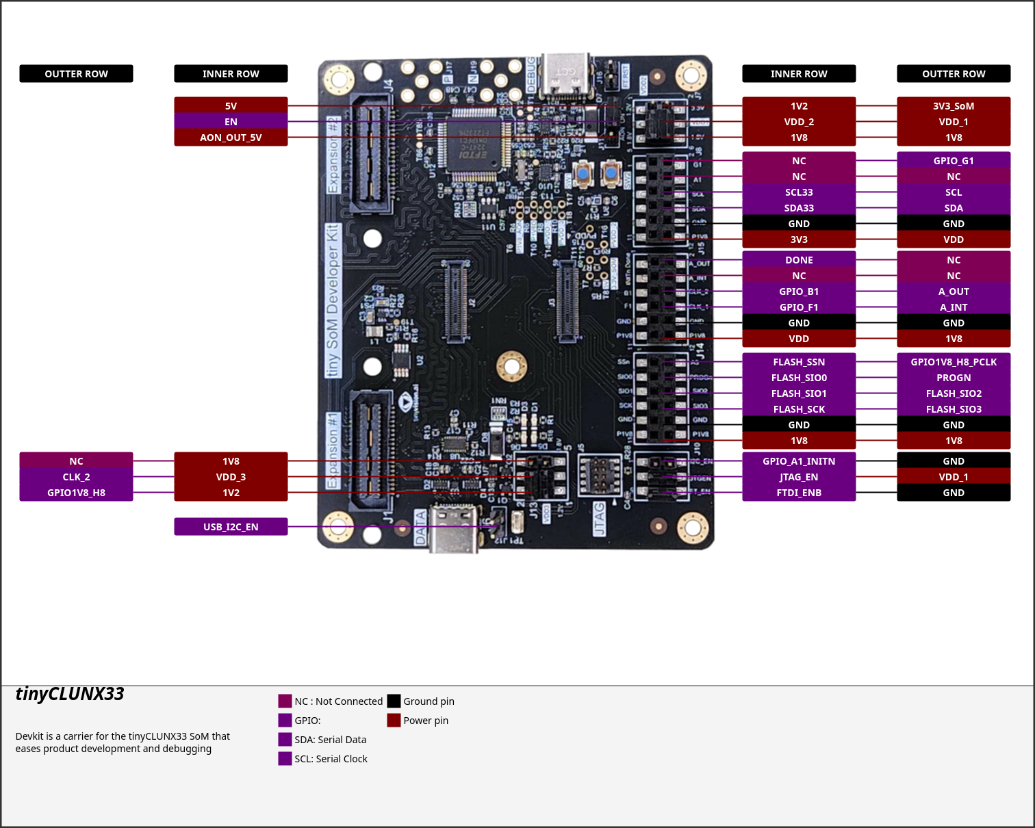
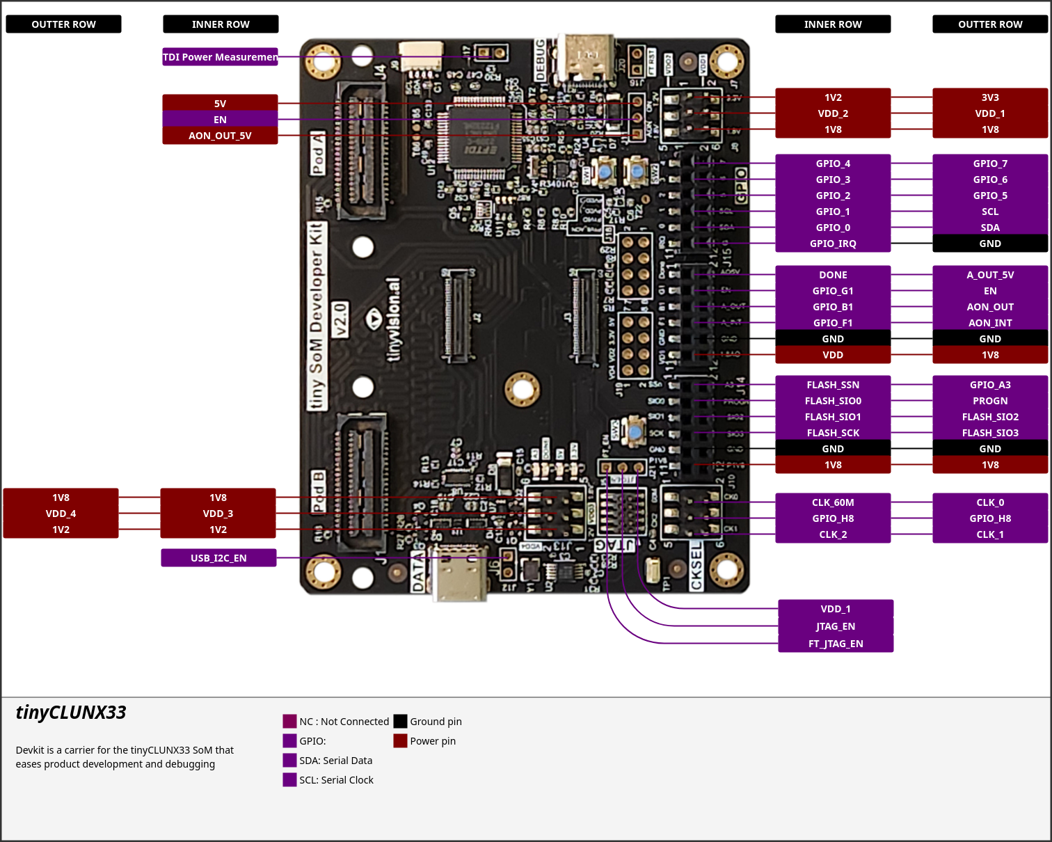
The Devkit is a carrier for the tinyCLUNX33 SoM that eases product development and debugging: A development kit usable as factory programming/test rig.


Features:
- All SoM pins exposed, additional probing and voltage pins
- Inexpensive 4-layer board, compact form-factor
- USB3 at 5 Gbit/s integrated with a Type-C port controller
- GPIO LED and push button
- FTDI chip for JTAG, Flash SPI, UART access over USB
Connectors:
- 2 - USB-C connectors for the FPGA 5 Gbit/s interfaces and FTDI debug
- 2 - QSE expansion connectors for adapter boards (RPi FPC Camera, custom...)
- 1 - SMA connector for the high-speed clock export
- 4 - headers for JTAG, SPI flash, I2C, GPIO
- Extra headers for EN signals and power rails
Mechanical:
- Components on one side with fewer exposed traces at the bottom
- No-tool setup of the SoM helping factory programming
- Mounting holes for securing the board in a rig or enclosure
Quick Start
These are the instructions to be able to quickly test the hardware, gateware, and firmware.
This assumes a command line environment: Linux terminal, Mac OSX terminal, Windows with WSL or Git Bash or OSS CAD Suite's MinGW or Radiant Programmer.
Follow the install instructions from the latest release page.
Then, unplug all USB cables to completely power off the board. Then, connect to the board using a serial console viewer, such as minicom, picocom, PuTTY, teraterm, or other tool of your preference.
The baud rate depends on the [RTL version]() selected: either 153600 or 192000, and all other parameters might be left to default.
The serial interface is the 2nd of the FTDI, for instance, on Linux, if the first interface of the FTDI is /dev/ttyUSB0, the logs would appear on /dev/ttyUSB1:
Then, pressing "Enter" should give an access to the Zephyr shell, displaying only uart:$.
Parts featured
- FTDI FT2232HL USB to Multipurpose UART/FIFO IC
- Diodes PI5USB30213A Type-C Dual Role Port Controller
- Samtec QSE-020-01-F-D-A-K High-Speed Socket connector
