Repositories
The tinyCLUNX33 has an open-core model:
tinyclunx33The open-source part: the base of the zephyr support: SoC and board definition and associated drivers and sample code.priv-tvai-usb: The private-access part with extra resources for using the tinyCLUNX33 as a high-bandwidth video system.
The dependencies are managed with West like any Zephyr project.
CI builds
The CI is rebuilding the firmware on every commit:
tinyclunx33CI builds images are accessible herepriv-tvai-usbCI builds images are accessible here
Building the firmware
This guide uses the tinyclunx33 sample application named zephyr_shell.
There are several targets for building the firmware, depending on what platform you wish to build on:
- Board:
tinyclunx33@rev1,tinyclunx33@rev2 - SoC:
rtl_1_0,rtl_1_1
Assuming a Board Rev2, a Devkit Rev2, and SoC RTLv1.0.3 being used:
- Follow the general Zephyr to setup the build environment for your platform: https://docs.zephyrproject.org/latest/develop/getting_started/index.html
- Reset the workspace directory you created from Zephyr's Getting Started Guide cd ~/zephyrprojectrm -rf .west
- Download the tinyCLUNX33 Zephyr example repository. This will also download the tinyVision Zephyr SDK as a dependency: Note: you may need to ask the access towest init -m git@github.com:tinyvision-ai-inc/priv-tvai-usbwest update
sales@tinyvision.aifor accessing this repository. - Apply the patch for upstream USB 3 support. west patch apply
- Build a sample application from this example repository, for instance
zephyr_cdc_rawfor RTLv1.0.3.cd priv-tvai-usb/zephyr/samples/usb_cdc_rawwest build --board tinyclunx33@rev2/rtl_1_1 - Then, program the firmware into the devkit, with the DEBUG interface connected. west flash
- Disconnect and reconnect the USB ports to power cycle the board, then you can see logs by connecting the DEBUG interface and use the 2nd serial console that shows-up, such as
/dev/ttyUSB1in Linux, at baud rate156200. Once connected, press the reset switch (SW2on the Devkit Rev 2) to see the early boot logs appear.
See also SoM Flash for other flash programming options.
You should now be able to see messages through the UART interface, a new USB Video Class (UVC) interface showing-up on your operating system, and if an IMX219 image sensor is connected, a video stream coming out of it.
Zephyr Configuration
This app note describes the particular Zephyr configuration layout of the tinyCLUNX33.
The tinyCLUNX33 platform consists of several elements stacked on each others:
- System-on-Chip (SoC) (
soc/tinyvision/tinyclunx33): describing the peripherals implemented by the FPGA. There is one SoC version for each FPGA system image version. Defined at the Zephyr level as an SoC. - System-on-Module (SoM): (
boards/tinyvision/tinyclunx33) describing the elements present on the tinyCLUNX33 module, defined at the Zephyr level as a board.
Zephyr Devicetree Configuraton
Most of the configuration boils down to devicetrees, which describe the topology of the hardware, and permit the build system to know what driver to select, and how to interconnect them.
The SoC, board and shield level all have variants according to the different versions of the hardware or RTL. The west build command allow to specify which version exactly to select.
The top level definition of the devicetree happens in the board directory, but these are only 1-line wrappers over the full configuration, located in the dts/riscv/tinyvision directory where all the content is:
- **
tinyclunx33_rtl_...:** in the public repo These files contain the top-level configuration for the various SoCs, describing all their content except the video-related content. - **
tinyclunx33_video:** in the private repo, describes all the video peripherals, but does not activate or interconnect them. - **
from_..._to_...:** in the private repo, are ready-made blocks that describe the interconnection between video devices. After includingtinyclunx33_video.dtsi, include the blocks you need to describe a chain of configuration that reflects your RTL topology.
Building a firmware for a particular SoC
These devicetree variants permit the firmware developer to swap the version of any part of the design at a firmware level:
For instance, one might be interested in testing a different RTL version, and for this, need to adapt the firmware to be built for the appropriate RTL version.
Or for instance, one might be building a same firmware going into the devkit, or a firmware going into a prototype, with different hardware on each case, which would need adaptation.
In order to adapt the firmware to all these different situations it is possible to pass flags to the west build command that will select the correct panaché:
Video Pipeline
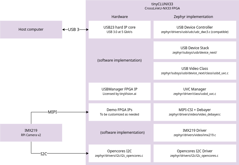
The tinyCLUNX33 is an FPGA module, where the VexRiscv CPU architecture is loaded from flash at runtime, in addition to the peripherals already provided by the FPGA fabric. Those are shown on the left of the diagram above.
On top of this, also from flash, the firmware is executed, with the Zephyr RTOS and drivers for each hardware elements. Those are shown on the right on the diagram above.
This shows the path of the data on each hardware element (left side, for I/O), and the software elements (right side, for control).
Video elements
- USB23 Hard IP: The CrossLinkU-NX33 comes with a hardware USB 3 MAC that can be pushed up to 3.4 Gbit/s at the application layer.
- USB Device Controller: The Zephyr-side driver for the USB23 IP. The hardware API is for the most part compatible with DWC3 register interface, inspired from the standard XHCI, but for device-side rather than host-side.
- USB Device Stack: The core implementation of USB is provided by Zephyr, and maintained by its contributors. It is not involved in the data path of USB in the case of the tinyCLUNX33, which allows to reach higher speeds than what software handling allows. However, all the enumeration process and the control comands are handled with software by this USB stack.
- USB Video Class: The handling of the UVC protocol, aka the "webcam protocol", with all the control commands interfaced to video API calls, further turned into I2C calls by the video driver.
- USB Manager FPGA IP: The FPGA core that handles the high-speed data transfer over USB, directly at the hardware level, without involving the CPU, directly from the video source to the USB endpoint.
- UVC Manager Driver: The Zephyr-side implementation, that configures the USB Manager FPGA IP at boot-time.
- Demo FPGA IPs: FPGA-side implementation of a basic image pipeline, including MIPI and debayer allowing to get an image out without correction. This is the element that a custom solution would modify to fit a particular input sensor, or several of them.
- MIPI-CSI + Debayer: The Zephyr-side driver for the Demo FPGA IPs that might be modified as well along with the FPGA side.
- IMX219 Driver: The Zephyr-side implementation of the IMX219 image sensor driver, sending commands over I2C according the the Video API. It receives the Video API calls from the UVC driver. This driver can be swapped with any other image sensor driver.
- Opencores I2C: An I2C controller that permits to communicate with the image sensor(s) and other I2C peripherals.
- Opencores I2C Driver: The Zephyr-side implementation of the I2C peripheral.
Pipeline driver setup
Like any Zephyr video driver, this video pipeline is using the devicetree to interconnect the drivers together. The syntax used is inherited from Linux taken as inspiration:
This shows an interconnection between two video processing elements: a source video0 upstream sending data to a video1 downstream.
The port and endpoint represent the input or output connection with the other video processing element, and the remote-endpoint-label specifies the name of the other endpoint with which the current endpoint is connected.
This forms a bidirectional reference between the two video elements that is used by the drivers to know what is the next and previous driver in the chain.
In order to facilitate the configuration, the tinyCLUNX33 video elements are already pre-integrated as seen here, and turned off by default.
This permits to keep the applications compact, which only need to turn on the drivers they use, as seen here.
The syntax to enable a core in Zephyr is:
The & of &video0 is there to refer to an existing node defined elsewhere.
Other driver parameters can be described as well in addition to status, for instance to change the default values provided by the global configuration.
See the Zephyr configuration for a detailed review of these configuration files.
Troubleshooting
The first sign of life from the Zephyr RTOS comes the UART interface, available by plugging the DEBUG USB cable.
In order to get early boot logs, you can hit the SW2 button which will reset the board but keep the serial console attached.
The Zephyr shell will be available over that same UART interface as the debug logs (except for the zephyr_shell sample code). For the Shell example, this goes through the DATA USB port, /dev/ttyACM0.
These debug commands permit to review the internal state of the various peripherals.
If nothing comes through the UART, see the FPGA troubleshooting section.
If getting any issue reproducing results, the CI job defined here will act as a verifiable and reproducible reference.
SDK-related errors version
Some errors might still be expected to expect around the SDK version, with the release of the Zephyr SDK v1.0.0:
In which case, running west sdk install can help installing a more recent version of the Zephyr SDK.